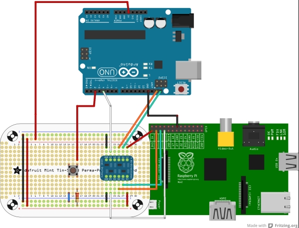
- ARDUINO UNO BOARD SCHEMATIC HOW TO
- ARDUINO UNO BOARD SCHEMATIC SERIAL
- ARDUINO UNO BOARD SCHEMATIC DRIVER
- ARDUINO UNO BOARD SCHEMATIC FULL
- ARDUINO UNO BOARD SCHEMATIC SOFTWARE
r a r d u i n o s a d i s c l a i m s a l l o t h e r a w a. Wiring the Analog Devices ADuM340E / ADuM341E / ADuM342E Quad SPI – Isolator with BOSCH BME280 Sensor | 14core. r e f e r e n c e u d e s i g n s a r e p r o v i d e d ' a s i s ' a n d ' w i t h u a l l t f a u l t s.Thomas on Wiring the 6 Digit 7 Segment 2.4 Inch HT1621 LCD Display Module on Microcontroller.Wiring MCP73831 + MAX17048 USB-C Single-Cell Fully Integrated Li-Ion / Li-Po Charge Management Controller with Fuel Gauge | on Wiring USB-C on Microchip MCP73831 a Single-Cell Fully Integrated Li-Ion / Li-Po Charge Management Controller.Build your Own Thermometer with ThingSpeak | on Wiring the MLX90614 Infrared Contactless Temperature Measurement Sensor on Microcontroller.The value of the resistor in series with the LED may be of a different value than 220 ohms the LED will light up also with values up to 1K ohm. In the diagram below we show an UNO board that has D13 as the LEDBUILTIN value. The Uno is the latest in a series of USB Arduino boards, and the reference model for the Arduino platform. Connect the short leg of the LED (the negative leg, called the cathode) to the GND. The Uno and version 1.0 will be the reference versions of Arduino, moving forward.
ARDUINO UNO BOARD SCHEMATIC FULL
"Uno" means one in Italian and is named to mark the upcoming release of Arduino 1.0. Full Arduino Uno R3 Schematic and BOM This schematic was developed using KiCad v4.0. The second one is a not connected pin, that is reserved for future purposes.
ARDUINO UNO BOARD SCHEMATIC SOFTWARE
Your design software should make it easy to use any Arduino mega pinout board, like the Arduino Uno PCB schematic, Mega, Zero, or another model.

In future, shields will be compatible with both the board that uses the AVR, which operates with 5V and with the Arduino Due that operates with 3.3V. If you want to modify an Arduino Mega schematic, you need design software that lets you easily build around an Arduino board and quickly add functionality. The app has three sections: a visual editor to create your circuits, a code editor that automatically generates test code for your components, and a guide area to help you build your project.
ARDUINO UNO BOARD SCHEMATIC HOW TO
I learned how to re-draw the schematic, modify it, I learned how to improve it and how to do PCB layout. Circuit.io Arduino Circuit Diagram Maker Circuit.io is a web-based prototyping tool designed for makers working with Raspberry Pis and Arduinos. 1.0 pinout: added SDA and SCL pins that are near to the AREF pin and two other new pins placed near to the RESET pin, the IOREF that allow the shields to adapt to the voltage provided from the board. I started with Arduino Uno reference schematic.So what is an Arduino It can basically mean two things: One, it is an open-source hardware and software company that creates circuit boards that makes microcontrollers easier to use. 3.3V Pin This pin supplies 3.3 volts of power to your projects. In here I will get into details with the basic arduino schematic diagram using one of their more popular development board, the Arduino UNO. DC Power Barrel Jack This is used for powering your Arduino with a power supply. Voltage Regulator This controls the amount of voltage going into the Arduino board. which rotates the FIGURE 4.94 The interfacing schematic of L293D and 5 V.
ARDUINO UNO BOARD SCHEMATIC DRIVER
Revision 3 of the board has the following new features: Power LED Indicator This LED lights up anytime the board is plugged in a power source. driver board, 5 V DC motor, and push-button switch with Arduino UNO board. Revision 2 of the Uno board has a resistor pulling the 8U2 HWB line to ground, making it easier to put into DFU mode. Instead, it features the Atmega16U2 (Atmega8U2 up to version R2) programmed as a USB-to-serial converter. The Uno differs from all preceding boards in that it does not use the FTDI USB-to-serial driver chip. Unlike the template for the Arduino Uno that comes with Kicad 5, this contains the full schematic for the Uno as a sub-sheet as well as the Unos BOM. It contains everything needed to support the microcontroller simply connect it to a computer with a USB cable or power it with a AC-to-DC adapter or battery to get started. It has 14 digital input/output pins (of which 6 can be used as PWM outputs), 6 analog inputs, a 16 MHz ceramic resonator, a USB connection, a power jack, an ICSP header, and a reset button.

ARDUINO UNO BOARD SCHEMATIC SERIAL
Some serial Arduino boards contain a level shifter circuit to convert. The Arduino Uno is a microcontroller board based on the ATmega328. So in this tutorial we will be looking into the schematic of Arduino Uno, modify it a little to our needs, make a PCB out of it and solder the required components to make the final product. Arduino is an open-source hardware and software company, project, and user community that.


 0 kommentar(er)
